The Jerk
Level 1 pedal assist was barely perceptible. Level 2 was a sudden jump. Level 3 and 4 felt nearly identical. The battery gauge would show three bars, drop to one within minutes, then climb back to two after a rest stop. Nothing matched the manual, a single photocopied sheet in broken English.
I could have bought a replacement controller for 80 euros. But I didn't want a new controller. I wanted to understand the existing one.
Hardware
The motor controller is a TranzX unit built around a Microchip PIC16F946, a mid-range 8-bit chip with 14-bit instruction words, 8 KB of program memory, and 336 bytes of SRAM. The kind of processor designed for washing machines and thermostats, not for projects anyone would bother reverse engineering. Which is probably why TranzX didn't invest in code obfuscation.
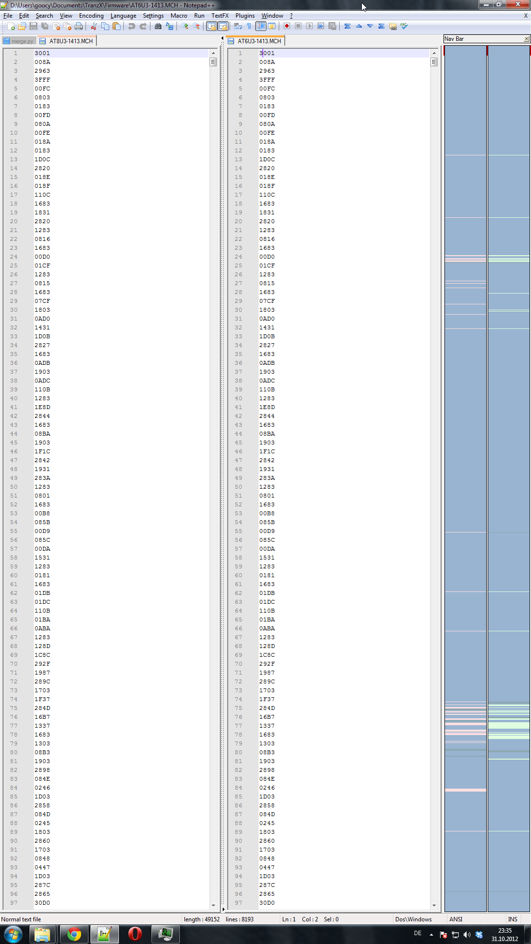
I sourced hex dumps for three firmware variants, SS606, SU806, and AT8U3, from an e-bike forum where other frustrated owners had extracted them with a PICkit programmer. My controller used SU806, but having multiple versions proved invaluable for telling intentional design apart from coincidence.
Reference Material
Before you can read disassembled firmware, you need to know the language. The PIC16F946's instruction set is small (35 instructions) but the addressing modes and register bank switching make raw disassembly hard to follow without constant lookups.
I created two CSV files: one for the instruction set (opcode, mnemonic, operands, cycle count, flags affected) and one for the special function registers (address, name, bit fields, reset value). Searchable tables instead of a 300-page PDF datasheet: this cut analysis time dramatically.
The EAGLE schematics for the controller board provided the other half of the context. Without knowing which GPIO pin connects to which physical component (motor MOSFET gate, battery voltage divider, pedal sensor, display data line), the firmware is just numbers being shuffled between registers. With the schematic, every register write becomes a physical action.
The Firmware
Four functional blocks:
Motor PWM control. The PIC generates PWM signals to drive the motor's MOSFET bridge, with duty cycle determining power to the motor. Each pedal assist level maps to a different base duty cycle, adjusted in real time by pedal cadence and current draw. The jump between level 1 and level 2 is disproportionately large because the firmware uses a non-linear curve, presumably tuned for a different motor than the one in my bike.
Battery monitoring. An ADC reads battery voltage through a resistor divider and applies a lookup table to convert voltage to bar count. The table has only five entries and no hysteresis. Under load, voltage drops below a threshold and the display shows fewer bars. Load decreases, voltage recovers, bars jump back up. A moving average or hysteresis band would fix it, but the firmware just does raw threshold comparison.
Pedal assist logic. A Hall sensor on the crank generates pulses; the firmware counts them over a time window to estimate cadence, then combines cadence with assist level to set the PWM duty cycle. Dead zone detection is aggressive: cadence drops below a threshold and motor assist cuts off completely instead of ramping down. This produces the jerky feel when pedaling slowly uphill.
Display communication. The handlebar display connects via bit-banged UART at a non-standard baud rate. Controller sends battery level, assist mode, and speed; display sends button presses. Undocumented but simple enough to reconstruct from the firmware.
Comparing Versions
Having three firmware variants let me distinguish design choices from hardware constraints. PWM frequency is identical across all three (likely dictated by the motor's electrical characteristics), but the assist level curves differ. The AT8U3 variant has a much smoother level 1-to-2 transition: someone at TranzX revised the tuning, probably in response to complaints.
The battery lookup tables also differ. Later versions have 7 entries instead of 5 and include crude hysteresis: a higher threshold for "bar up" than for "bar down." Someone heard the same complaints I had.
What I Took Away
With 35 instructions and 8 KB of program memory, there's not much room for abstraction. The code is direct, almost conversational once you learn the idioms.
The disassembly itself was straightforward. The bottleneck was constantly switching between the instruction reference, the register map, and the schematic; consolidating those into searchable CSV files was the single biggest productivity gain. And reading code you can't run is its own skill: no debugger, no breakpoints, no printf, just register states and branch targets, the entire execution model built in your head.
I never modified the firmware. Bricking the only controller for my daily commute bike felt like an unreasonable risk. But the analysis told me what I needed to know: the non-linear assist curves and missing hysteresis aren't bugs. They're firmware that was "good enough" for the target price point and never revisited.